The Principle of Infrared Radiometry
The method of measuring infrared radiation temperatures – also called quantitative infrared thermography and pyrometry – is based on the physical phenomenon that objects with a temperature above absolute zero (0.0 K or -273.15 °C) emit electromagnetic radiation. If its intensity can be determined, the temperature of the emitting object can be calculated without any contact.
Infrared Radiation in the Electromagnetic Spectrum
Infrared radiation is the part of the electromagnetic spectrum of the long-wave side of the visible spectrum starting with red light at wavelengths of ca. 760 nm and extending to around 1 mm.

For the technical measurement of temperature, what matters, however, is the range of wavelengths down to around 20 µm. This range can be divided into the following sections:
| Wavelength | Section of Infrared |
| (0.8 … 2) µm | Near infrared |
| (2 … 6) µm | Mid-infrared |
| (6 … 20) µm | Far infrared |
Please Notice
The terms near, mid and far infrared are used in many German and English publications for the above (or similar) limits. More correct is the use of SWIR, MWIR, LWIR. Often the LWIR range is also extended to 14 µm.
Infrared Radiation is Similar to Visible Light – With the Exception of the Wavelength:
Propagation in all directions without the need for the presence of matter.
The highest speed of propagation is the speed of light (reached in a vacuum).
Validity of the optical laws
Laws of Thermography
Radiation as a Function of Temperature
From a thermodynamic point of view, temperature is a measure of the internal energy of a body. The internal energy is based, among other things, on the movement or oscillation energy of the molecules, atoms and electrons. The higher the temperature, the greater this energy, which can be explained by the faster movements of the particles above. If the temperature is 0 K (absolute lowest temperature with -273.15 °C), the particles do not move.
The speed of the particle movement – and thus also the energy level of the same – thus depends on the temperature. The particles emit energy from time to time in the form of electromagnetic radiation and a photon as they change to a lower energy level. Other particles in the body absorb the photon and the radiation energy and thus reach a higher energy level. Within the body, a balance is established between energy emission and absorption. The process described here corresponds to heat conduction within a body.
At the body boundary, on the other hand, energy is released in the form of electromagnetic radiation and photon emission, insofar as the environment has a lower temperature than the body. If, on the other hand, the environment is warmer than the body, the process takes place in the opposite direction: the body absorbs energy from the environment and warms up; its internal energy thus increases.
Another interesting correlation can be observed: With higher temperature, the particles not only move with higher speed, they also change their energy level more often and faster. Therefore, the amount of energy radiated increases steadily with temperature, as does the frequency of the radiation (the wavelength shortens).
Radiation Laws of the Black Body
The objects used in practice have a great variety of radiation characteristics. Thus, it has proven useful to observe the simplified regularities of a model object with ideal radiation characteristics first and then apply them to the actual objects. In radiation physics, this ideal body is called a blackbody. It has the greatest intensity of emitted radiation of all bodies at the same temperature.
The following laws play an important role for thermography
STEFAN BOLTZMANN law
WIEN’s law
PLANCK’s radiation law
STEFAN BOLTZMANN Law
If we look at the amount of radiation emitted by an ideal radiator as a function of temperature, we find that the amount of radiation depends on the fourth power of the temperature. This relationship is called STEFAN-BOLTZMANN's law:

The simplicity of this mathematic equation makes it very good for rough estimates, especially for calculations of the thermal economy of objects and for the pyrometrics of entire objects. The spectrum measurement range of most measuring instruments, however, is generally quite limited and thus precludes the application of this equation.
WIEN’s Law
The chart for PLANCK’s law of radiation shows that the wavelength at which the radiation emitted by a blackbody reaches a maximum change according to the temperature. WIEN’s law can be derived from the differentiations in PLANCK’s law.

The lower the temperature of the object to be measured, the more the maximum radiation shifts towards longer wavelengths. Near room temperature, this is around 10 µm.
Maximum Radiation Relative to Temperature
| Object | Temperature | Maximum Radiation |
| Deep-freeze food | -18 °C | 11.4 µm |
| Skin | 32 °C | 9.5 µm |
| Boiling water | 100 °C | 7.8 µm |
| Iron, growing red | 600 °C | 3.3 µm |
| Iron, glowing brightly | 1,200 °C | 2.0 µm |
PLANCK’s Radiation Law
PLANCK’s radiation law describes the spectral distribution of the radiation emitted by a blackbody:

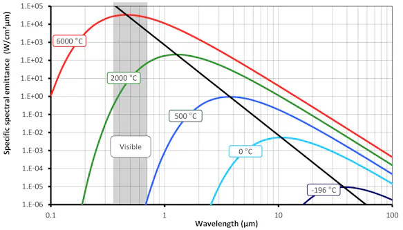
This visualization shows that the spectrum of the radiation emitted varies when the temperature of the object changes. For instance, objects with temperatures above ca. 500 °C also emit visible radiation. Furthermore, the intensity of the radiation for each the wavelength increases as the temperature rises.
By integrating the spectral radiation intensity over all wavelengths, the quantity for the total radiation emitted by the body is obtained. This calculation is similar to the application of STEFAN-BOLTZMANN law. WIEN's displacement law is obtained by differentiating PLANCK's equation.
The Measuring Object
The blackbody as a physical radiation model is indispensable for the study of the underlying principles. As practical measuring objects more or less deviate from this model, it may be necessary to calculate for this influence for measurements. Here, the parameter of the degree of emissivity – a measure of the ability of a body to emit infrared radiation – can be used. The blackbody has the value 1, the best emissivity possible, which also applies for all wavelengths.
In contrast, the emissivity of real objects more or less depends on the wavelength. In addition, the following parameters may influence the results:
Material composition
Layers on the surface
Angle to surface normal
Temperature
A multitude of – at least in the long-wave range – has high, relatively constant emissivity irrespective of the surface composition. Human skin and most mineral construction and painting materials are a few examples.
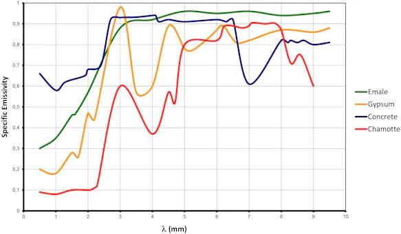
Furthermore, a distinction is made between light and dark non-metals, which have different emissivities depending on the wavelength range. The resulting relationships from the point of view of practical thermography can be summarised as follows:
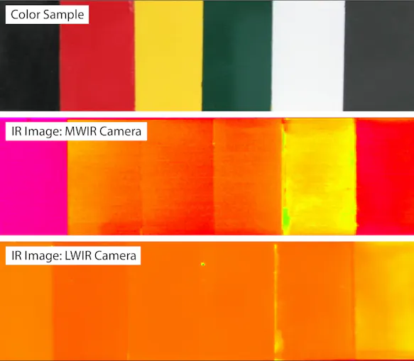
LW range (8 ... 14) µm:
Dark and light non-metals have almost identical emissivities.
Colour differences therefore have no significant influence on the measurement result.
MW range (2 ... 5) µm:
Dark and light non-metals have clearly different emissivities.
Thus, the influence on the measurement result is significant in the case of colour differences.
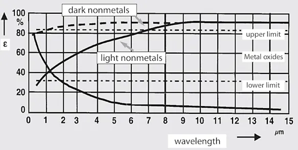
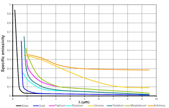
Compared to non-metals, metals generally have a low emissivity, which is strongly dependent on the surface properties and decreases sharply towards longer wavelengths.
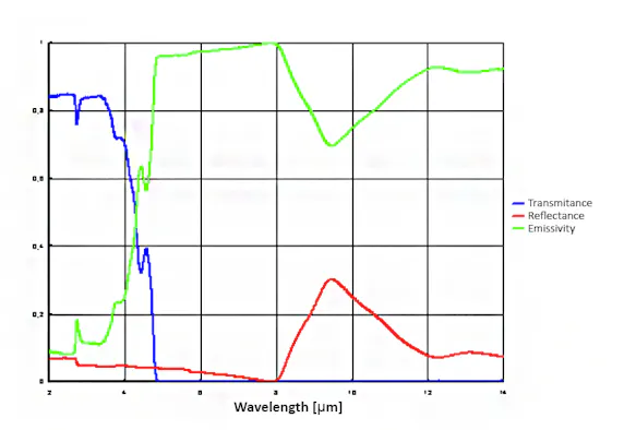
Glass is a relatively common material in metrological practice. This material is opaque to infrared radiation in the long-wave spectral range, so that measurements through window glass using long-wave infrared measuring instruments are not possible. In contrast, glass has very good transmission properties for short- and medium-wave infrared radiation up to 3.5 µm, on the basis of which temperature measurements through glass using medium-wave infrared measuring instruments (with filters) are possible. While glass behaves almost like a black body in the spectral range between 5 µm and 8 µm, its emissivity in the long-wave spectral range is only approx. 85 %.
Dependence of the Emissivity on the Surface Roughness
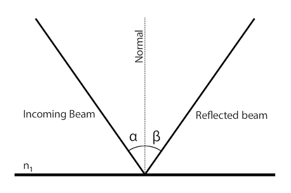
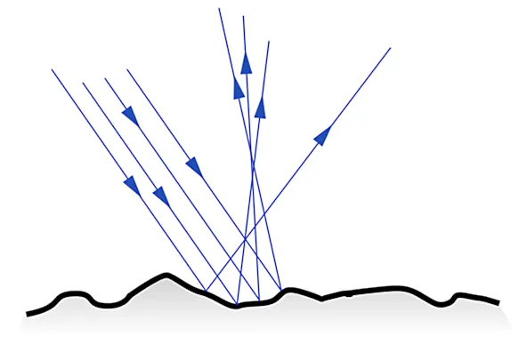
The rougher an object surface, the higher the emissivity to be expected. For non-metals with material-dependent high emissivities, this plays only a minor role, but for metals (with normally low emissivities) the surface roughness has a great influence on the emissivity. The explanation for this is that, for example, polished metals represent mirrors with directional reflection (and high reflectance), whereas rough surfaces cause diffuse reflection (whereby the radiating surface is orders of magnitude larger than with the polished surface) and, in addition, there is a self-blackening effect.
Dependence of the Emissivity on the Viewing Angle
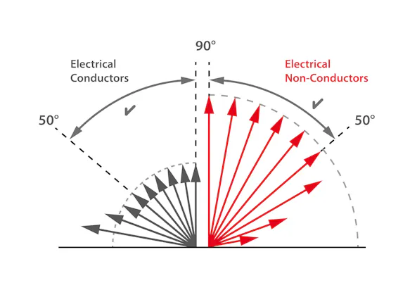
Depending on the material, a change in emissivity can be observed depending on the viewing angle. While in the case of electrical non-conductors an almost constant (mostly high) emissivity can be observed up to a viewing angle of approx. 50°, but then increasingly sharply decreasing, in the case of conductive materials the emissivity increases increasingly at viewing angles below 50°. The highest emissivity can be recorded at extremely acute viewing angles. These correlations must be taken into account in particular when evaluating thermograms of curved surfaces.
Emission, Reflection, Transmission
So far, we have only dealt with the emissivity as a measure of the body's ability to emit radiation. For practical temperature measurement, however, the other radiation-related physical properties of the objects to be measured should not be neglected.
The body-specific measurement numbers of the radiation-related body properties are:
Emission factor ε: Measure of the body's ability to emit radiation (emission).
Absorption factor α: Measure of the body's ability to absorb radiation.
Transmission factor τ: Measure of the body's ability to transmit radiation (transmission)
Reflection factor ρ: Measure of the body's ability to reflect radiation (reflection).
The above factors are each a ratio compared to an ideal radiation model and are therefore used without a unit (0 ... 1) or as a percentage (0 ... 100) %.
KIRCHHOFF's law states that the emissivity and absorptivity of a body - related to the same radiation wavelength – is always the same.

The black body radiator (emission factor ε = 1) is therefore an ideal radiator and at the same time also an ideal radiation absorber.
According to the ENERGY CONSERVATION LAW, the following relationship between the above factors also applies:

The following special cases can be derived from both laws:
| Designation | Definition | Derived Properties |
| Ideal emitter | ε = 1 | τ = 0, ρ = 0 |
| Ideal mirror | ρ = 1 | ε = 0, τ = 0 |
| Ideal window | τ = 1 | ε = 0, ρ = 0 |
| Non-transparent object | τ = 0 | ε + ρ = 1 |
It follows from the derived properties that the temperature of ideal mirrors, as well as ideal windows, cannot be detected by means of non-contact methods (pyrometry, thermography), since both types of bodies do not emit radiation. Thus, there is no radiation that is related to their own temperature.
Measuring Arrangements
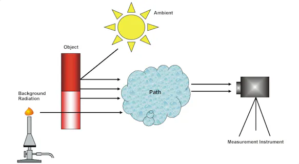
The relationships described so far refer to the properties of the object to be measured and its influence on the non-contact temperature measurement. From the point of view of practical temperature measurement, however, the properties of the measuring section, the measuring device and the presence of sources of interfering radiation in the foreground and possibly in the background of the object to be measured also play a decisive role.
Influence of the Measurement Path
Since infrared thermography is a non-contact method, the infrared radiation from the object to be measured to the measuring device must pass through a "transmission" medium whose infrared optical properties can influence the measurement result. In most cases, this medium is air, but other materials such as infrared-transmissive "windows" also occur in practice.
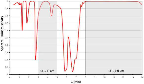
The transmission (transmittance) of air is very strongly wavelength-dependent. Areas of high attenuation alternate with areas of high transmittance (highlighted in grey), the so-called "atmospheric windows". While in the range (8 ... 14) µm, the long-wave atmospheric window, the transmission is uniformly high even over large distances, in the range (3 ... 5) µm - the middle atmospheric window - measurable attenuations due to the atmosphere already occur at measuring distances of several tens of meters. In particular, the air components water vapor and carbon dioxide have an influence on the transmission of infrared radiation.
Influences by the Thermographic Camera
Because of the atmospheric windows discussed in the previous section, measuring devices for non-contact temperature measurement have very limited spectral measurement ranges and therefore only detect a fraction of the radiation emitted by the measurement object. The following diagram shows the effect of spectral limitation on measurement sensitivity for some typical spectral ranges.
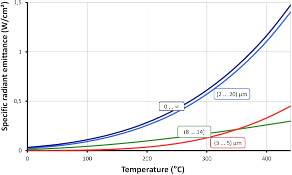
At temperatures above approx. 350 °C, the radiation intensity available in the spectral range (3 ... 5) µm is higher than in the spectral range (8 ... 14) µm. In contrast, temperatures below 0 °C in the spectral range (3 ... 5) µm can only be measured with low sensitivity, and above approx. -100 °C practically not at all. Bodies of this temperature do not emit any practically measurable medium and short-wave infrared radiation (see PLANCK's law of radiation).
Pyrometric / Thermographic Basic Equation
In order to display the correct object temperature, the influences described in the previous chapters must be taken into account and compensated for mathematically. The means for this is the thermographic basic equation derived in the following.
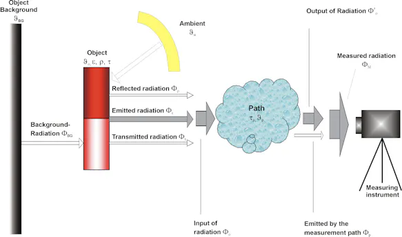
The radiation Φ emitted by an object of temperature ϑO with emissivity ε calculated as follows:

with Φ(ϑO) describing the radiation emitted by a blackbody of the same temperature. In addition, two other radiation shares are emitted by the surface of the object:

These two shares combine with the object to create the radiation intensity that travels the measurement path:

In the case that is most important in practice – a non-transparent object - τ = 0 and the equation

are simplified into:

and the resulting, simplified equation for the intensity of the radiation emitted by the object is:

It is then weakened when it passes the measuring path relative to the degree of transmission:

In addition to the radiation that travels the measuring path, the measuring instrument registers the radiation emitted by the measuring path itself:

with this share being calculated as follows:

which gives us:

If this value is then entered into the equation for the radiation emitted by an object, the following model typically used for a thermography device or pyrometer is the result:

Adjusted for the desired size and object temperature O, the following term is to be continually determined during the measurement by the measuring instrument:

Here, Φ(ϑ) is the measuring instrument’s specific temperature as determined by its temperature characteristics (cf. Radiation-temperature curves for different spectral ranges), with Φ-1 being its reverse function.
As this mathematic equation suggests, the following parameters are also taken into consideration for the calculation of the object’s temperature in addition to the measured radiation intensity ΦM:
ε ... emissivity of the object being measured
ϑU ... ambient temperature
τP ... degree of transmission of the measuring path
ϑP ... temperature of the measuring path
In frequent cases where the measurement path is so short that no significant influence of the infrared radiation occurs due to interaction with the measuring path exposed to radiation, this equation is usually formulated as follows:

Here, the ambient temperature enters into the measurable radiation intensity for degrees of emissivity that differ by 1 and hence must be taken into consideration for corrections of the degree of influence on emissivity.
Otherwise, in cases for the ideal blackbody, the equation is simplified further and only consists of the inverse function of the temperature characteristics of the measuring instrument. The ambient temperature is not calculated into the measured temperature:

Thermal Resolution
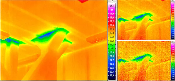
In many cases, especially when the range between room temperature and the lower temperature limit of the measurement is to be measured – this parameter is decisive for the quality of the image as it reflects the share of “noise” in the infrared image. NETD stands for “noise equivalent temperature difference” and describes the change in object temperature relative to the effective value of the devices own noise (usually at 30°C). Be careful with other temperature information as this value increases greatly as the object’s temperature drops, especially with short-wave devices. Though the “noiselessness” of the image for the viewer depends on the selected temperature range, a rough NETD value can be based on 1/100th of the temperature interval to be displayed, e.g. 0.1 K for a common interval of 10 K in building thermography.
Geometric Resolution / Field of View Size
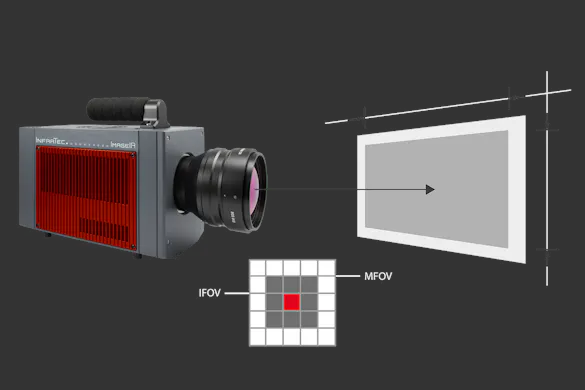
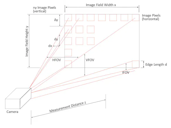
In addition to the thermal resolution, the geometric resolution considerably influences the image quality that is possible with a thermography device. The parameter IFOV (instantaneous field of view) describes the angle recorded from one single field of view. This value has to be as small as possible for the details to be reproduced well. For instance, a value of 1.5 mrad indicates that the single measuring point assigned to each pixel at a distance of 1 m has a diameter of 1.5 mm. Keep in mind that this value is relative to the optics used; see whether the objective used is suitable for its image field before assessing this parameter.
While some thermographic cameras are offered with exchangeable lenses, others can be used with supplementary zoom, wide-angle, or macro-lenses. All of these varieties have one thing in common: they aim to cover an area as large as possible for possible image field – the horizontal field of view (HFOV) and vertical field of view (VFOV) as well as the image distance. However, it should not be forgotten that an optical enlargement of the field of view – by whatever means – also entails an enlargement of the single measuring spot. (In other words: the geometric resolution deteriorates when the field of view is enlarged).
Frame Rate and Selection Technologies
Fast infared camera systems with a frame rate ranging up to some kHz open thermography doors to new applications. The thermal behaviour of high speed processes can be monitored and analysed. An example is the optimisation of airbags as the heat distribution during the explosion can well be analysed.
High-speed thermography with frame rates of more than 100 kHz are based on special detectors and acquisition units. Especially their ability to acquire and read out data in parallel provides thermographic measurements precisely in a millisecond range. Those detectors are so-called snapshot detectors which are integrated by InfraTec in their ImageIR® infrared camera series.
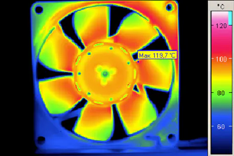
Measurement Result
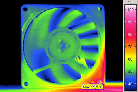
Apart from the geometric resolution, the number of image pixels influences the quality – or more precisely the level of detail – of the thermal image that can be achieved with a thermographic camera. The reason for this is that a sufficient number of pixels must be allotted to the object in order to be able to recognise its shape and structure - the same situation as we are used to in digital photography. It is therefore easy to understand that with a higher number of pixels, either the given object surface can be captured in greater detail or a larger object area can be captured with the same level of detail.
If a thermographic camera has only a few pixels, many small-area images must be taken in order to achieve the appropriate level of detail, which must then be mounted for documentation or reporting. This is particularly necessary if an overview of the entire object surface is required for evaluation (e.g. longer apartment blocks, extensive circuit boards, larger machine groups, drying ovens, etc.).
The number of pixels is an extremely important parameter in the case of thermographic cameras. While we are talking about resolutions of more than 10 megapixels for digital cameras, thermographic measurement systems typically have 320 x 240 (76,800), 384 x 288 (110,592) or 640 x 480 (307,200) pixels. Low-cost IR cameras even have just 160 x 120 (i.e. only 19,200) pixels, which means that only extremely small object areas can be measured and displayed with sufficient detail. Despite their low price, this severely restricts the areas of application for such cameras, since much higher measurement and evaluation costs have to be calculated, which in turn leads to significantly higher labour costs.
Thanks to the rapid development of detector technologies, thermographic cameras with (1,024 x 768) or (1,920 × 1,536) IR pixels are available today, which offer this resolution even with up to 105,000 Hz recording frequency.
For special tasks, the resolution of the FPA detectors can be quadrupled by using MicroScan technology. Here, the micro-movement of the optical system deflects the radiation image by half a pixel (horizontally and vertically in each case) and thus also records an image point where the gap in the detector matrix was previously located.
The Correct Measurement
Influence of Errors on Non-contact Temperature Measurement
Like every measuring device, a non-contact temperature measuring device (pyrometer, thermographic camera) also has a certain – process- and device-specific – measuring error, but its influence on the temperature measurement result is much lower than the errors caused by the measuring conditions and possible operating errors. Possible sources of error (ordered by their influence on measurement error) are the problems listed below:
Remaining error of the measuring transformer after individual calibration of the device
Non-compensated deviations for changes of the temperature of the measuring instrument
Quantization error of the digitalization, processing, and output / display of measurement values
Drift of transformer parameters due to aging
Note
The influence of the measurement inaccuracy of the measuring device on the accuracy of the non-contact temperature measurement is, however, far below the extent of the measurement errors caused by the previously mentioned error sources.
Incorrect Setting of Emissivity and Ambient Temperature for the Measuring Instrument
This is easily the most important cause of the – sometimes considerable – errors caused by methods in contactless temperature measurements in practice. As showed in the previous section, the measuring instrument can only determine the temperature of an object correctly, if the settings for emissivity on the measuring instrument correspond to the real characteristics of the object measured. This is only trivial if the measured object is a blackbody with emissivity of =1.0. If this setting for emissivity deviates from this value, the ambient temperature is also calculated for in the measurement value and must also be set correctly. The mean temperature in space around the inner surface of the measured object is taken as the ambient temperature.
Reflection of Perturbing Radiation from the Front of the Object
For the correction of emissivity that takes place in the measuring instrument (or afterwards with software-supported analysis) and is necessary whenever the infrared radiation characteristics of the object significantly differ from the ideal of the blackbody, the value of the ambient temperature is used for corrections. This is always problematic when area in the front of the object has greater deviations due to lack of homogeneity or even spot sources of perturbing radiation.
Signal Losses due to Weakening Radiation on the Transmission Path
Generally, the transmission path consists of common atmosphere (cf. fig. 4), in which infrared radiation across much of the infrared spectrum (called the atmospheric window) is hardly influenced across large distances. The situation is different for deviating characteristics (such as fog, aerosols, high concentrations of CO
Transmission of Perturbing Radiation from the Back of the Object
This type of error occurs rarely when the object is partially transparent. In such cases (measurements on foils, gases, materials that partially transmit infrared light), the background of the object is to be taken into consideration just as the front is for reflections. This can be especially problematic when the object is to be measured by a row of radiators directly behind it during the technologically necessary heating process.
Quantitative View of Errors
Based on the thermographic basic equation, it is numerically possible to calculate the maximum temperature measurement error resulting from a misadjustment of the emissivity, the ambient temperature or the transmission of the transmission path.
Errors in Temperature Measurement due to Emissivity
In the following, the share of the whole temperature measurement error can be calculated for the error due to deviation between the settings for the emissivity of the object with the actual value.
| Incorrect setting of emissivity eps | Temperature measurement value (C°) | |||||||
| To=60°C eps=0.9 |
To=60°C eps=0.5 |
To=60°C eps=0.2 |
To=20°C eps any |
To=10°C eps=0.9 |
To=10°C eps=0.5 |
To=10°C eps=0.2 |
||
| -0.10 | 53.4 | 56.6 | 74.4 | 20.0 | 8.7 | 7.3 | -1.3 | |
| -0.08 | 52.7 | 54.9 | 66.6 | 20.0 | 9.0 | 8.0 | 2.6 | |
| -0.06 | 51.9 | 53.6 | 61.0 | 20.0 | 9.2 | 8.5 | 5.3 | |
| -0.04 | 51.2 | 52.2 | 56.6 | 20.0 | 9.5 | 9.0 | 7.3 | |
| -0.02 | 50.7 | 51.2 | 52.9 | 20.0 | 9.9 | 9.5 | 8.7 | |
| 0 | 50.0 | 50.0 | 50.0 | 20.0 | 10.0 | 10.0 | 10.0 | |
| +0.02 | 49.5 | 49.0 | 47.5 | 20.0 | 10.2 | 10.4 | 10.9 | |
| +0.04 | 48.8 | 48.0 | 45.6 | 20.0 | 10.4 | 10.7 | 11.7 | |
| +0.06 | 48.3 | 47.1 | 43.6 | 20.0 | 10.7 | 11.2 | 12.4 | |
| +0.08 | 47.8 | 46.3 | 42.2 | 20.0 | 10.9 | 11.4 | 12.9 | |
| +0.10 | 47.3 | 45.6 | 40.7 | 20.0 | 11.0 | 11.7 | 13.4 | |
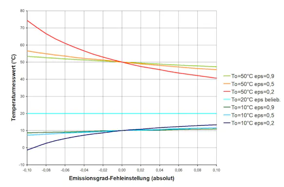
It will be seen that this error is greater the more the object temperature deviates from the ambient temperature. It will also be seen that the influence of the error can quickly become so great that it overshadows the measuring instrument’s intrinsic error several times over.
The following chart shows that the error in temperature measurement relative to the characteristics of the object can represent quite a source of error.
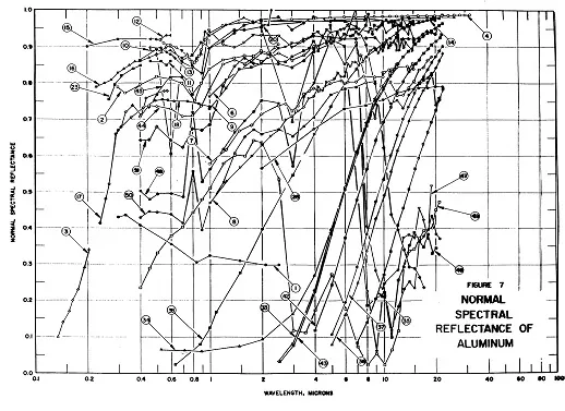
In practice, a determination of the emissivity properties of metals is hard to gather from literature for the purposes of contactless temperature measurement. Usually, it is almost impossible to find literature that refers to the conditions (spectral range, surface, extent of corrosion, etc.) that one finds on a specific object. Experimental determination is the most promising solution.
Measurement Error due to Inaccurate Focusing
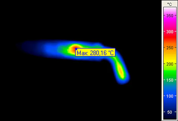
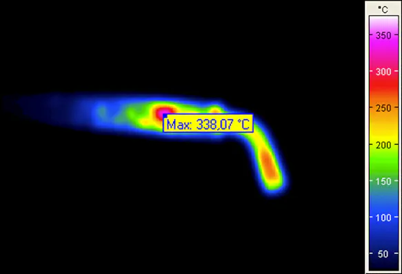
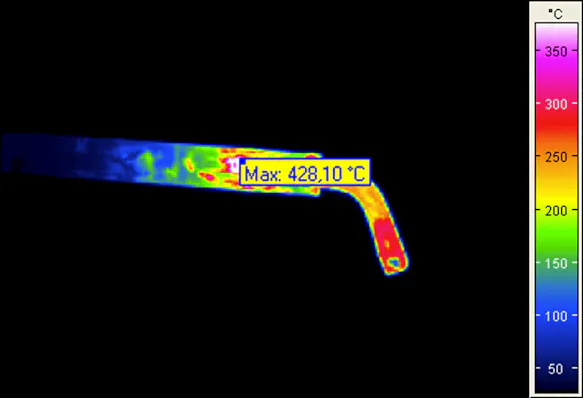
In the theoretical discussion of non-contact temperature measurement, it has already been pointed out that the radiation that can be detected by the detector depends on the optical system of the infrared measuring system. Special attention must be paid to the focussing, among other things, as poor adjustment of this – contrary to the common misconception – leads not only to a blurred thermal image, but also to falsified measured values.
The optical focus in thermographic systems works in exactly the same way as in photography: the task of the collecting or focus lens in the camera is to concentrate the radiation on the detector surface (in traditional photography on the film, in digital photography on the sensor). If the focus is poor, the rays are "collected" already before or only after the detector surface, which leads to a blurred image (which cannot be corrected afterwards).
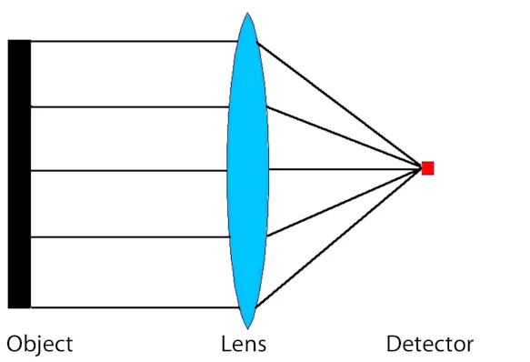
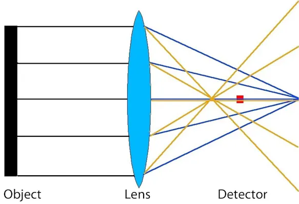
In the case of thermographic measurements, however, the problem is much more serious: since only part of the radiation reaches the sensor, generally only a smaller amount of radiation is used to calculate the temperature and therefore overall lower temperatures are measured than the actual ones. Local maximum values are therefore generally lower than the real maximum object temperatures. However, radiation from pixels with higher temperatures also reaches surrounding pixels with lower temperatures due to poor focusing. For these pixels, a temperature value is calculated based on a part of the own radiation and a part of the radiation of the warmer neighbouring pixel, which can therefore also be higher than the actual pixel temperature.
Effect of inaccurate focusing on the temperature readings:
Measurement Error due to Non-observance of the Geometric Resolution
As already mentioned with the camera parameters, in addition to the thermal resolution, the geometric resolution also has a considerable influence on the image quality and accuracy of the measurement results that can be achieved with a thermographic system.
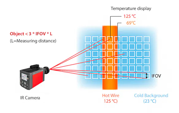
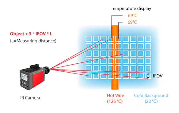
The size of the individual measuring spot assigned to each pixel can be determined for a given object distance using the numerical information for the parameter IFOV "Instantaneous Field of View". However, since it is not known where exactly this measuring spot is located, there is a risk that it is only partially located on the object. To determine the smallest possible measurable object size, the above value of the measuring spot dimension must therefore be doubled.
The above consideration assumes that the individual detectors join each other on the detector matrix without gaps (this would correspond to a fill factor of 1). However, the FPA detectors have a gap between the individual detectors due to technological necessity. Smaller errors in the optical imaging must also be expected. Therefore, for safety, instead of doubling, one applies a tripling of the single spot diameter to determine the minimum object size.
Example calculation
Distance: 2 m
IFOV: 1.5 mrad
Single spot on an object at 2 m distance: 2 x 1.5 mm = 3 mm
Smallest measurable object: (3 x 3) mm = 9 mm
An exception is the use of the MicroScan technology as this technology achieves a fill factor of 1 (or above) and the gap in the detector matrix thus practically "disappears".
Keep Geometric Resolution in Mind
If the geometric resolution is not observed, the object temperature and the background temperature are averaged. The measured values do not correspond to the real object temperature and can deviate upwards or downwards depending on the background temperature!
Ways to Minimise Errors
Error influences due to reflected or transmitted sources of interference radiation during a thermographic measurement can usually be easily identified immediately (during the measurement) by their optical appearance (point or circular objects in the image) and thus eliminated. A subsequent correction is usually not so easy. It is therefore advisable to observe the following instructions, which serve to suppress temperature measurement errors caused by interfering radiation and reflection:
Before starting the measurement, the measurement set-up should always be checked for reflections from sources of interference radiation. If present, one or more of the following measures can be taken to remedy the situation:
Changing the location of the measuring device and thus the viewing angle.
Changing the location or inclination of the measurement object (especially for laboratory measurements)
Shielding of sources of interfering radiation by means of infrared-impermeable materials (paper, cardboard, expanded polystyrene, PMMA, etc.), in extreme cases complete enclosure of the object to be measured with the exception of an opening for the lens of the measuring instrument.
Check the Sources of Interference Radiation
In addition to obvious sources of interference radiation such as incandescent lamps, flames, etc., machine parts or even people can also be considered as such, depending on the reflection properties of the measured object and the requirements for the precision of the measurement.
If the emissivity of the object to be measured deviates significantly from that of the black body, it must be set on the measuring device with the smallest possible deviation from reality. The information about the emissivity to be set can be obtained in different ways:
Experimental determination on the real measurement object or a characteristic reference object with comparable infrared radiation properties.
Use of self-obtained information or information provided by suppliers about the specific material in its typical state during the measurement.
Search for literature data on emissivities of samples of the same material as the one to be measured with surface properties that are as comparable as possible.
Pay Attention to the Ambient Temperature
If the emissivity setting differs from 1.0, the set ambient temperature is included in the temperature reading. In this case, it must be ensured that the ambient temperature (average radiation of the reflected ambient objects) is also set correctly.
If you measure in the medium-wave spectral range over distances from approx. 10 m, it is important to also include the influence of the radiation intensity by the limited atmospheric transmission in the correction. In this case, it is important to set the temperature of the measurement path as correctly as possible in addition to the transmission value itself.
