Use of High-speed Thermography in Laser High-temperature Capillary Gap Brazing
Lasers are extremely versatile tools in industry and manufacturing technology. Due to their flexibility, they serve as a key technology for implementing the goals of industry 4.0. Although laser cutting and welding are nowadays regarded as turnkey technologies, the majority of laser applications, for example joining of hybrid materials, 3D printing or ultra-short pulse processing, still require considerable research and development.
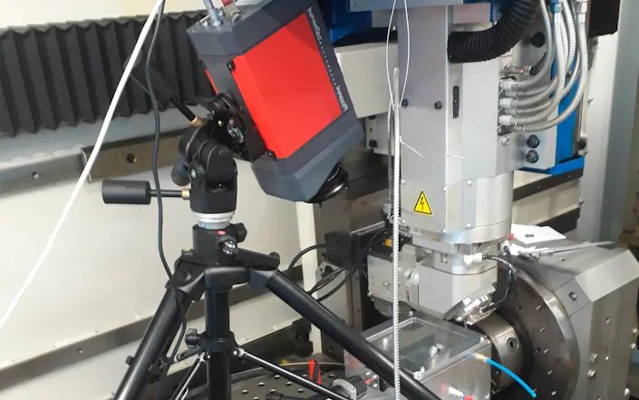
The LaserApplicationCenter (LAC) of Aalen University intensively researches and develops new methods of laser material processing. Thus, innovative materials for Additive Manufacturing are developed and investigated within public R&D projects, including magnetic materials or electrical energy storage materials for electromobility. Another focus is lightweight construction. Here, among other things, mixed metallic compounds and hybrid lightweight structures made of aluminium and CFRP for CO2-efficient mobility concepts are investigated. The newly developed processes aluminium laser polishing and high-temperature capillary gap brazing are already being used in industrial projects.
InfraTec Solution
Aalen University
LaserApplicationCenter (LAC)
M. Hofele, D. Kolb, S. Ruck, H. Riegel
www.hs-aalen.de/en
Thermography system
ImageIR® 8300 hp
Making Heat Flow Visible
Laser processes are highly dynamic thermally induced processes that cannot be detected with the naked eye. High-speed visual cameras that are often used are not capable of visualising the heat flow in the component. A contacting temperature measurement of the moving very small liquid metal is not possible. In addition, the processing zone should remain free of influences from the measurement system. This is exactly what thermographic cameras do, which provide high frame rates with high spatial resolutions at the same time.
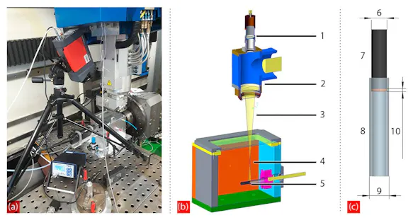
1 Pyrometer Optics
2 Welding Head
3 Laser Beam
4 Focus
5 Soldering Sample
6 Ø 7.9
7 Inner Pipe
8 Outer Pipe
9 Ø 10
10 Soldering Ring Ø 1.5
Specially Configured Thermographic Camera within Laser Material Processing
Laser-based production involves special requirements on the use of a thermographic camera. One reason for this are the processing temperatures of typically 500 °C to 2,000 °C. In addition, the components of the camera must be protected against sputters, caused by the machining process. If the laser manufacturing processes take place in process chambers under a specific atmosphere, the measurement section is enriched with a gas. Especially the optics of the camera must be protected from the reflected laser radiation. It is therefore equipped with a laser protection lens for solid-state lasers and a filter for through glass and high-temperature measurement. Due to these precautions, the camera can be used in close proximity to the laser beams without any problems.
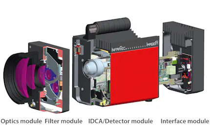
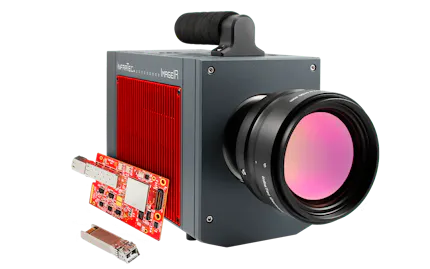
Configured appropriately, the thermographic camera ImageIR® 8300 hp from InfraTec supports the LAC with its high spatial and temporal resolution. Using the camera's MicroScan function, images can be taken with a spatial resolution of more than one megapixel. The 10 GigE interface allows fast data transmission up to 355 Hz in full frame mode. Due to the optical package consisting of a telephoto lens with 50 mm focal length and the close-up lens for reducing the minimum focusing distance down to 170 mm, the researchers can easily adapt the camera to changing working distances and sizes of the measured objects.
Analysing the Temperature Control Behaviour During Laser Beam High-temperature Soldering
The LAC of Aalen University, together with its industrial partner conntronic Prozess- und Automatisierungstechnik GmbH from Augsburg, is investigating laser high-temperature capillary gap brazing of corrosion-resistant steels for tube assemblies in automotive and mechanical engineering within the framework of the publicly funded research project “enAbLe”. In contrast to induction and furnace brazing, the laser beam serves as a flexible and highly efficient tool. The challenge lies on the one hand in the required highly pure reduction process environment to remove the oxide layers for good wetting of the copper solder and on the other hand in the homogeneous tempering of the joining zone. For homogeneous heating, the laser beam is controlled to the desired process temperature of 1,300 °C by means of a coaxially integrated high-speed pyrometer with sampling rates of several kilohertz. In addition to temperature control, the exposure strategy has a decisive influence on the formation of the temperature zones. Besides the FEM simulation, the thermographic camera is used for process development in the empirical experiments.
The experiments take place in a six-axis TLC 1005 laser cell with an infrared 4 kW disc laser TruDisk 4002. The test geometry consists of a tube plug connection, austenitic chrome-nickel steel 1.4301, with outer tube diameters of 10 mm and 7.9 mm. Three weld spots offset by 120° fix the pipe-plug connection. The solder is pure copper from Voestalpine in the form of a solder ring (see figure before, 1c). The oxygen-reduced process chamber used for the tests has a laser-permeable beam entry window in the lid. The soldering tests are carried out in a forming gas atmosphere with a residual oxygen content of less than 150 ppm. The atmosphere is monitored by means of a residual oxygen measuring device. During the process, the soldering assembly, clamped in a three-jaw chuck, rotates around the pipe axis by an external rotary machine axis. The laser beam is defocused to a diameter of 9 mm and radially tempering the outer surfaces of the joining zone (see figure before, 1b). The beam centre is oriented centrically to the solder ring.
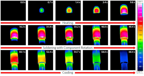
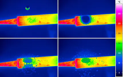
The laser soldering process is divided into three phases: heating, soldering with component rotation and cooling. During the heating phase of 10 s (see figure, upper row), the laser heats the facing component surface to the control temperature of 1,300 °C in a stationary manner. During the soldering phase (see figure, middle row) the assembly performs a complete rotation with an angular speed of 540 °/min. After the copper solder depot has been molten, the solder gap filling starts at 31.9 seconds. Due to the lower emission of copper, the forming fillet appears cooler than the surrounding steel surface of the joining partners. Because of the very good thermal conductivity of the solder, the through heating of the inner tube also starts at this point (difference between picture at 16.3 s and picture at 31.9 s in the figure). At the end of complete rotation and shutdown of the laser, the component cools to below 600 °C within 18 s (see figure, lower row).
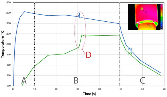
A Heating
B Component Rotation
C Cooling
D Inserting the soldering gap filling
P1 Max. Pixel Temperature
P2 Max. Pixel Temperature
The measurement data of the thermographic camera allows a versatile process analysis afterwards. The diagram in the upper figure shows the temperature-time sequence of two measurement points, P1 in the laser spot centre and P2 on the inner tube. The dynamic temperature changes in the gap filling process stand out in this context.
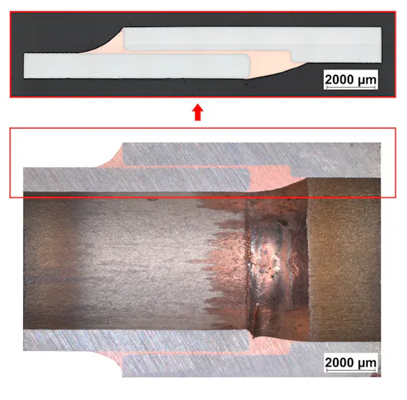
The figure shows the longitudinal cross section through the faultless laser soldered tube plug connection. The presented sample shows a complete gap filling without porosity. The evenly formed grooves on both sides ensure a good distribution of force and low-turbulence flow inside the pipe.
Due to the evaluation of further thermographic data, the temperature control strategy could be further optimised and soldering times of less than 10 s could be realised.
Collecting Important Process Knowledge
With regard to laser soldering, thermography provides important insights into process development. Thus, optimised path planning for optimal heating can be identified and at the same time the thermal load of the surrounding zones can be reduced. The LAC aims to achieve comparable results with similar tasks. With the help of the thermographic camera, for example, the temperature distribution gets recorded in each layer at the 3D metal printing process of selective laser melting. The focus lies primarily on the heating and cooling behaviour of the used materials, which has a direct effect on the structure quality that is formed.
