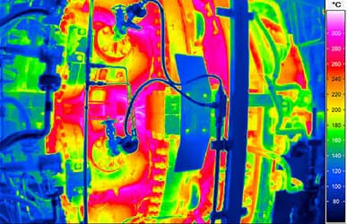
Infrared Thermography for Determining Heat Transfer Coefficients
Technical systems and devices are often subject to the influence of thermal energy or heat up due to internal processes. Their efficiency and service life can be increased, for example, by optimised thermal management. The installed active components are usually optimised extensively for this purpose. Passive components, on the other hand, are often neglected in this respect.
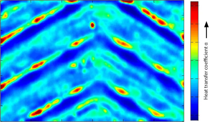
Research activities, such as those at the Institute of Thermodynamics of Leibniz University Hannover (IfT), show that there is great potential for reducing energy requirements and increasing power densities. Scientists there use infrared thermography to analyse the heat transfer to surfaces in order to increase it in the future by means of suitable measures.
InfraTec Solution
Leibniz University Hannover
Institute of Thermodynamics
www.ift.uni‐hannover.de
Infrared camera
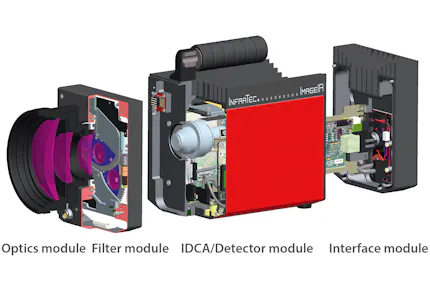
ImageIR® 8300
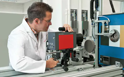
Passive components include, for example, housings of devices, pipes of technical equipment or parts of heat exchangers. Their heat‐transferring surface can be increased by implementing ribs, 3D structures and plates. In addition, structures on the surface of pipes and plates cause turbulences in the flow, which facilitate the heat transfer. "It is precisely this heat transfer that we would like to determine reliably," says Marco Fuchs of the IfT. "At the same time, there are numerous questions to consider. What influences the flow and thus the heat transfer? Is the measurement method actually non‐reactive to the examined thermal process? How can local values also be measured? "Based on these considerations, the IfT decided to determine the heat transfer without contact by identifying the thermal behaviour of the test object using the ImageIR® 8300 infrared camera from InfraTec. More specifically, Marco Fuchs and the entire research team rely on the Temperature Oscillation Infrared Thermography (TOIRT) method.
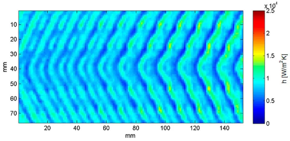
TOIRT Method for the Contactless Measurement of Heat Transfer
For the analysis, the outside of a flow‐carrying test object, such as a plate heat exchanger or pipe, is excited with an oscillating heat flow by lasers or halogen lamps. As a result, its surface temperature changes, the temperature change is detected with the ImageIR® 8300 and recorded over a certain period of time. The recorded sequences then arrive as single frames via an import in Matlab.
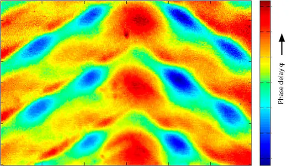
The next step is the calculation of the phase delay. "To put it simply, we measure how much time elapses between the excitation with the heat flow and the corresponding temperature response of the test object," says Marco Fuchs. The phase delay is calculated from this value and corrected again using mathematical operations such as the single frequency discrete Fourier transformation. The periodic duration of the stimulation does not have to be known for this method. All information can be determined from the temperature response of the test object.
Subsequently, a mathematical model of the wall of the test object emerges, which takes all relevant boundary conditions into account, such as the excitation by a heat flow and the heat transfer coefficients on the outside and inside of the wall. The main research interest is the heat transfer coefficient on the side of the wall facing away from the camera, e.g. the inside of a tube. A start value is assumed for the heat transfer and a phase delay between the excitation and temperature response is calculated. The phase delay calculated by a 3D model is then compared with the measured phase delay. The heat transfer on the inner side is adjusted in the calculation model by means of the deviation. This process is repeated until the calculated phase delay coincides with the measured phase delay. This occurs in parallel for each pixel of the infrared camera detector. As a result, the scientists subsequently obtain an exact pixel resolution of the heat transfer coefficient. The resulting image is thus derived from a calculation based on a time‐dependent temperature signal.
The average heat transfer coefficient can thus be calculated for the viewed image section by means of averaging. If, for example, the measurement object is a radiator, this calculation can be used to check whether it flows evenly on the inside or whether deposits have a negative influence on the flow and thus on the heat transfer.
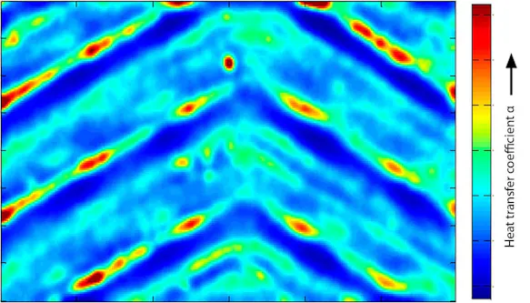
Infrared Camera with High Spatial and Thermal Resolution Necessary
"The temperature oscillation method offers us key benefits. We can act non‐invasively and neither distort the flow nor the thermal behaviour of the surface of the test objects and thus not distort the heat transfer either. Moreover, even low energy inputs are sufficient for the tests, since small heat flow densities and small temperature differences allow reliable calculations", explains Marco Fuchs.
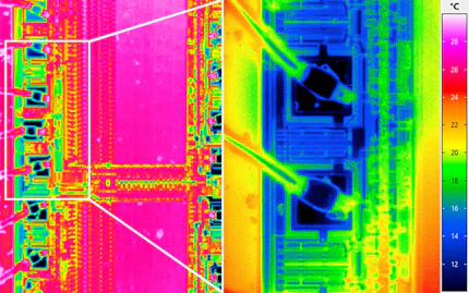
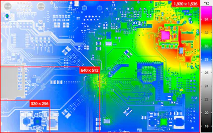
During the actual measurement, the high spatial and thermal resolution of the ImageIR® 8300 in conjunction with the telephoto lens used, which has a focal length of 100 mm, prove to be of benefit. The detection of even the slightest temperature differences is of particular interest when fine surface structures are used to improve the heat transfer. Subsections of the structure, which are often smaller than 1 mm, are usually responsible here for increasing the heat transfer. Thanks to the infrared camera's detector format of (640 × 512) IR pixels, such structures can be analysed reliably.
Should the scientists want to go into even more detail in the future, they can do so confidently. Since in addition to the telephoto lens, the ImageIR® 8300 can be extended by a macro lens. As a result, a large working distance of 50 cm, which quickly becomes necessary for measurement objects with very high temperatures, allows structural sizes of up to 75 μm to be displayed.
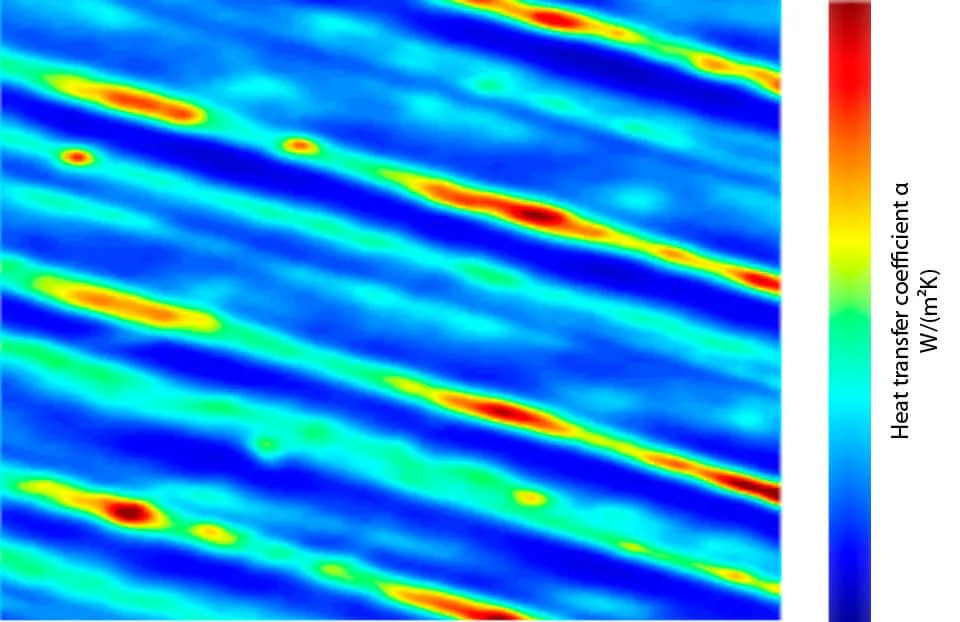
"Even the high frame rate is crucial for us," says Marco Fuchs. "Our method is based on the phase delay between thermal stimulation and temperature response. Thanks to the full‐frame frequency of 100 Hz, we are able to clearly identify the exact beginning of the temperature response."
Based on the previous analyses, the scientists at the IfT will continue to validate the parameters of the various correlations. In addition to infrared thermography, technologies such as computational fluid dynamics (CFD) should be used to better understand and determine flows and heat transfer.
